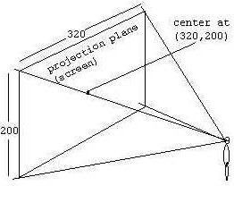
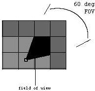
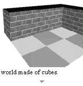
<<PREVIOUS | TABLE OF CONTENTS | CONTINUE >> FLOOR CASTING (Continued) The math behind floor-casting is explained in the Figure 25 below. Figure 25: The math behind floor-casting. To reiterate, take a look at the illustration while reading these steps: * Start from the bottom of the wall slice. Take the pixel position (you have this […]

<<PREVIOUS | TABLE OF CONTENTS | CONTINUE >> DRAWING FLOORS To draw floors, we can perform floor-casting (floor-casting refers to a techique of rendering floors). Note however, that it would be wasteful to perform floor-casting without texture mapping or shading. In other words, if the floor is not to be textured or shaded (shading will be […]

<<PREVIOUS | TABLE OF CONTENTS | CONTINUE >> TEXTURE MAPPED WALLS To make the walls more attractive, the walls can be painted with texture (bitmap) using a technique known as texture mapping. (Texture mapping in general refers to a technique of painting a bitmap/texture onto a surface.) For the cube world, we use bitmaps that have […]

<<PREVIOUS | TABLE OF CONTENTS | CONTINUE >> RAY-CASTING STEP 5: DRAWING WALLS In the previous steps, 320 rays are casts, when each ray hits a wall, the distance to that wall is computed. Knowing the distance, the wall slice can then be projected onto the projection plane. To do this, the height of the projected […]

<<PREVIOUS | TABLE OF CONTENTS | CONTINUE >> RAY-CASTING STEP 4: FINDING DISTANCE TO WALLS There are several ways to find the distance from the viewpoint (player) to the wall slice. They are illustrated below.   Figure 17: Finding distance to a wall slice.   The sine or cosine functions are cheaper to implement because they […]

<<PREVIOUS | TABLE OF CONTENTS | CONTINUE >> To find walls, we need to check any grid intersection points that are encountered by the ray; and see if there is a wall on the grid or not. The best way is to check for horizontal and vertical intersections separately. When there is a wall on either […]

<<PREVIOUS | TABLE OF CONTENTS | CONTINUE >> RAY-CASTING STEP 3: FINDING WALLS Notice from the previous image (Figure 11), that the wall can be viewed as collection of 320 vertical lines (or 320 wall slices). Figure 12 This is precisely a form of geometrical constraints that will be suitable for ray-casting. Instead of tracing a […]

<<PREVIOUS | TABLE OF CONTENTS | CONTINUE >> By knowing the field of view (FOV) and the dimension of the projection plane, we can calculate the angle between subsequent rays and the distance between the player and the projection plane. These steps are illustrated inFigure 11 (Many books define these last two values arbitarily, without telling […]

<<PREVIOUS | TABLE OF CONTENTS | CONTINUE >> RAY-CASTING STEP 2: DEFINING PROJECTION ATTRIBUTES Now that we have the world, we need to define some attributes before we can project and render the world. Specifically, we need to know these attributes: 1. Player/viewer’s height, player’s field of view (FOV), and player’s position. 2. Projection plane’s dimension. […]

<<PREVIOUS | TABLE OF CONTENTS | CONTINUE >> Before we begin, let’s examine the limitation of ray casting. LIMITATIONS OF RAY-CASTING Ray casting is fast because it utilizes some geometric constraints. In most cases, walls are always at 90 degrees angle with the floor. (Note that we are not talking about the angle between walls and […]